Home
Fantech Fr 150 Wiring Diagram . Page 2 of 4 page 3 of 4 Product may need to be returned to the
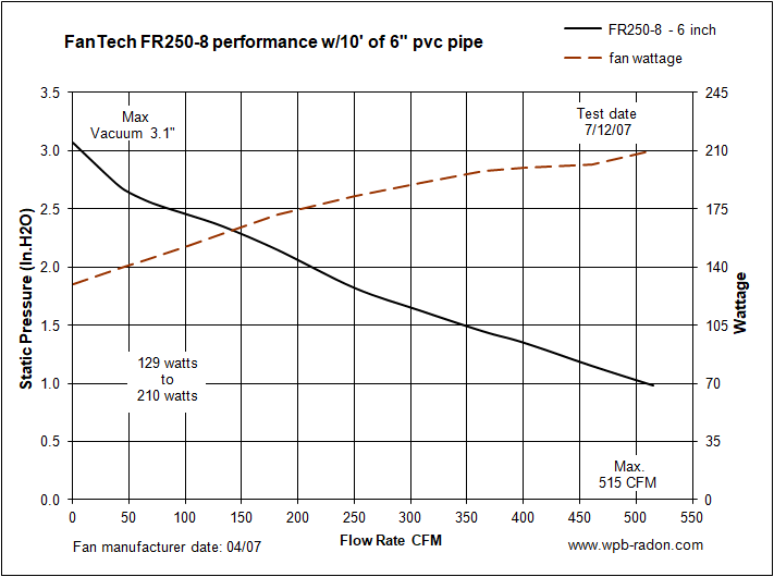
Fantech All Fantech Fans Fr100 Fr150 Hp190 Hp220 Hp2133 Hp2190 Fr250 8 Rec10xl Hp190sl Rn4ec 4 Pfedk Rn2ec 4 Rn1 Rn2 Rn3 Pds150 Radonaway All Radonaway Fans Gp201 Gp301 Gp401 Gp501 Gx5 Rp145 Rp140 Rp260 2 from www.wpb-radon.com Please visit our website www.fantech.net for more detailed technical. Connect the incoming power supply directly to the fan motor as shown in fr110 wiring diagram below. Fantech's fr series fans have long been the choice of. Product may need to be returned to the View & download of more than 429 fantech pdf user manuals, service manuals, operating guides.
The fan on the dryer will stop but you should still hear air being pulled through the dryer from the booster fan. When autocomplete results are available use up and down arrows to review and enter to select. Ideally tailored performance curve for a vast majority of your mitigations. Page 2 of 4 page 3 of 4 Remove the pressure switch leads from the wiring terminal block c. The fan on the dryer will stop but you should still hear air being pulled through the dryer from the booster fan. Fantech reserves the right to modify, at any time and without notice, any or all of its products' features, designs,.
Source: img.photobucket.com Refer to the fans by fantech product selection program for details of other combinations. This video demonstrates the ford f150 complete wiring diagrams and details of the wiring harness or connectors. If fan fails to start, please consult fantech for additional technical support.
Wiring must be in accordance with as/nzs3000:2007 and local supply regulations. See wiring diagram (figure 1). An led light on the indicator panel lets the user know that the fan is operating correctly.
10048 industrial blvd lenexa ks 66215. See wiring diagram (figure 1). Ford f 150 factory radio uninstall and new install adventures in diy.
Source: shop.fantech.net Installation instructions is part of fantech's technical library that is designed to give fantech customers appropriate information about installation instructions, adjustable pitch axial flow fans, motor types and specifications, noise & acoustic, installation & maintenance instructions and installation guide on what to do's and don'ts. Ltd and be of the model numbers shown on the schedule/drawing. See wiring diagram (figure 1).
A wiring diagram is a simplified standard photographic representation of an electric circuit. Bearings are of the 'sealed for life' type and will not need a detailed. Ford f 150 factory radio uninstall and new install adventures in diy.
See wiring diagram (figure 1). Hp/fr series inline radon fans. Fantech makes air quality control easy thanks to decades of research, development, and refinement that continue to push the industry forward.
Source: www.hvacquick.com Bearings are of the 'sealed for life' type and will not need a detailed. See wiring diagram (figure 1). Fantech reserves the right to modify, at any time and without notice, any or all of its products' features, designs,.
Turn on power to fan. Turn on power to fan. The fans feature a fully sealed plastic housing.
Wiring diagram the ducting from this fan to the outside of the building has a strong effect on the air flow, noise and energy use of the fan. Touch device users, explore by touch or with swipe gestures. Installation instructions is part of fantech's technical library that is designed to give fantech customers appropriate information about installation instructions, adjustable pitch axial flow fans, motor types and specifications, noise & acoustic, installation & maintenance instructions and installation guide on what to do's and don'ts.
Source: images.cmsnl.com Ford f 150 factory radio uninstall and new install adventures in diy. Protection fuses in the circuit should be regarded as protecting the wiring only against short circuit, they are not suitable for overload protection. If fan fails to start after blowing into the tubing:
Ford f 150 factory radio uninstall and new install adventures in diy. Inline fan, 6 inline duct fan w/plastic housing, 120v, 1~ description a centrifugal type exhaust/supply fan specifically designed for moderate size ventilation applications. Fantech your ventilation solutions company 3 electrical connection 1.
The fans feature a fully sealed plastic housing. 10048 industrial blvd lenexa ks 66215. Fan, dehumidifier user manuals, operating guides & specifications
Source: shop.fantech.net When autocomplete results are available use up and down arrows to review and enter to select. Wiring diagrams are provided with all fans. Inline fan, 6 inline duct fan w/plastic housing, 120v, 1~ description a centrifugal type exhaust/supply fan specifically designed for moderate size ventilation applications.
It reveals the elements of the circuit as streamlined shapes, and also the power as well as signal links between the tools. Shown in fx4xl wiring diagram below. Option 1 figure 1 return air duct that closes when the hrv is not operating.
Touch device users, explore by touch or with swipe gestures. Option 1 figure 1 return air duct that closes when the hrv is not operating. If fan starts, consult fantech for additional technical support.
Source: data2.manualslib.com Learn which fantech solution is the best fit in your next project today. Ltd and be of the model numbers shown on the schedule/drawing. 1996 freightliner fl70 fuse box diagram.
The fan on the dryer will stop but you should still hear air being pulled through the dryer from the booster fan. If fan fails to start, please consult fantech for additional technical support. Ideally tailored performance curve for a vast majority of your mitigations.
1991 dodge pickup wiring diagram sbec diagrams bait road. See wiring diagram (figure 1). The fan on the dryer will stop but you should still hear air being pulled through the dryer from the booster fan.
Thank you for reading about Fantech Fr 150 Wiring Diagram , I hope this article is useful. For more useful information visit https://thesparklingreviews.com/
