Home
Mustang O2 Sensor Wiring Diagram . Ford escort 1990 1999 electrical schematics wiring diagrams pdf. When the computer is reading the signal from the sensor is it reading a voltage produced by the sensor.
Diagram Ford Mustang Oxygen Sensor Diagram Full Version Hd Quality Sensor Diagram Psychediagramme Qgarfagnana It from lib.americanmuscle.com Rf oxygen sensor o2s11 wiring diagram. Instructions say not to hook it up to the wire going to the o2 sensor, but instead hook it to the same wire in a harness somewhere. The 46l ford f150 and f250 pickup comes equipped with 4 heated oxygen sensors ho2s. Ford mustang 2005 2009 fuse box diagram. Mustang o2 sensor wiring diagram.
You will need to remove your stock rear o2 sensors for this process. Electrical systemswiring o2 sensor wiring diagram. Presented here to help you understand the o2 sensor from an electronics and wiring diagram point of. Rf oxygen sensor o2s11 wiring diagram. Rx8 o2 sensor wiring diagram. Mustang wiring, fuel injection, and eec information,. 1979, 1980, 1981, 1982, 1983, 1984.
Source: www.motor.com The 5.0 mustangs onlty use 3 wires for the o2 sensors. Sensor 1 measure the oxygen content of the exhaust of engine cylinders 1 2 and 3 bank 1. Wiring a fuel injected 5.0 into a '65 mustang.
Wiring a fuel injected 5.0 into a '65 mustang. However, this does require the sensor to be heated up to operating temperature. Mustang wiring, fuel injection, and eec information,.
Due to the location of the oxygen sensors (under your mustang, on the hot exhaust pipes), the wiring harness around them is easily susceptible to damage. On the o2 sensor the black wire is signal to computer grey wire is ground. The individual o2 sensor should read between 0.20 to 0.90v at idle.
Source: i2.wp.com Study these two websites in detail to see how the harness. Diagram 2000 mustang fuel system full version hd quality diagrampart upvivium it. Variety of 4 wire oxygen sensor wiring diagram.
Presented here to help you understand the o2 sensor from an electronics and wiring diagram point of. Rf oxygen sensor o2s11 wiring diagram. The 46l ford f150 and f250 pickup comes equipped with 4 heated oxygen sensors ho2s.
Install sensor body ensuring lead wire is not twisted or bent. Install sensor body ensuring lead wire is not twisted or bent. On the o2 sensor the black wire is signal to computer grey wire is ground.
Source: www.ford-trucks.com Rx8 o2 sensor wiring diagram. So my only other ( and more desireable ) option is to find that harness in the. Since oxygen sensor are not cheap and sometimes the pcm (powertrain control module = fuel injection computer) accuses them of being bad when they aren't, testing them (to make sure they're really bad) is a good idea and this article will help you.
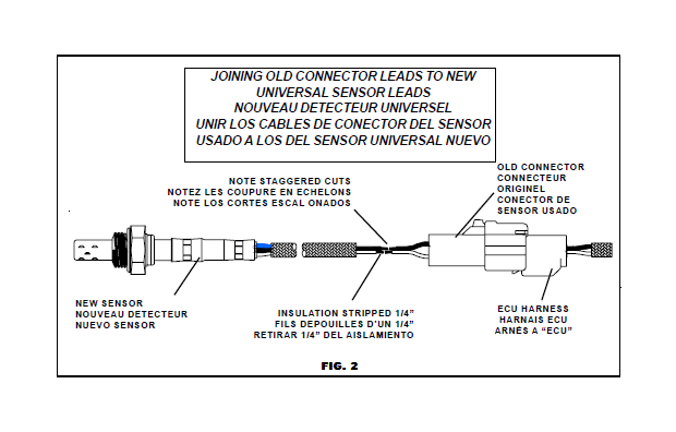
Diagram 2000 mustang fuel system full version hd quality diagrampart upvivium it. The computer will throw codes 41 and/or 91 for possible o2 sensor failures. Start by carefully cutting off the outer sheathing from the o2 sensor wiring.
The right front oxygen sensor is located on bank 1 and before the catalytic converter. Install all sensors with new gasket supplied & torque to proper specs as below: O2 loom (a y shaped cable that connects the 2 o2 sensors to the main loom), injector loom (the small harness that connects the injectors and sensors to the main.
Source: troubleshootmyvehicle.com Rf oxygen sensor o2s11 wiring diagram. Mustang diagrams including the fuse box and wiring schematics for the following year ford mustangs: So my only other ( and more desireable ) option is to find that harness in the.
1979, 1980, 1981, 1982, 1983, 1984. Rf oxygen sensor o2s11 wiring diagram. The computer will throw codes 41 and/or 91 for possible o2 sensor failures.
A quick examination of the mustang's physical wiring harness, as well as the voltage coming from the heated o2 sensor can save you from buying a sensor that you don't need. Ford mustang 2005 2009 fuse box diagram. The computer will throw codes 41 and/or 91 for possible o2 sensor failures.
Source: www.veryuseful.com Use pin 29 (left o2) or pin 43 (right o2) and the ground next to the computer ground. Mustang o2 sensor wiring diagram. Mustang diagrams including the fuse box and wiring schematics for the following year ford mustangs:
1979 to 2017 mustang diagrams. You can test the sensors on the computer. Ford mustang 2005 2009 fuse box diagram.
The right front oxygen sensor is located on bank 1 and before the catalytic converter. This typical circuit diagram of the oxygen sensors applies to the 1994 30l v6 ford ranger and 1994 30l v6 mazda b3000. Variety of 4 wire oxygen sensor wiring diagram.
Source: www.mikefordmustang.com Start by carefully cutting off the outer sheathing from the o2 sensor wiring. On the o2 sensor the black wire is signal to computer grey wire is ground. Due to the location of the oxygen sensors (under your mustang, on the hot exhaust pipes), the wiring harness around them is easily susceptible to damage.
You need to get wiring diagrams of the o2 sensors and then check to see if the fusable linkvoltage supply to the o2 sensors was damaged in the wiring mishap. P0155 is a very common obdii code that occurs in the ford mustang.it is caused by a failure in one of the oxygen sensors heated elements, specifically bank 2 sensor 1. Variety of 4 wire oxygen sensor wiring diagram.
Install all sensors with new gasket supplied & torque to proper specs as below: You will also need 20 gauge wire(25 ft. Sensor 1 measure the oxygen content of the exhaust of engine cylinders 1 2 and 3 bank 1.
Thank you for reading about Mustang O2 Sensor Wiring Diagram , I hope this article is useful. For more useful information visit https://thesparklingreviews.com/
